The Tesla Coil Through Time
How it came to be and why.
Nikola Tesla was a unicorn person before “unicorn person” became a term.
He was a Serbian inventor who came up with the idea of wireless energy transfer among things like alternating current, induction motors and many others.
I would say that he built out his idea of global wireless energy transfer in three phases. The very first was the Tesla Coil, which I made a video about. You can check it out below.
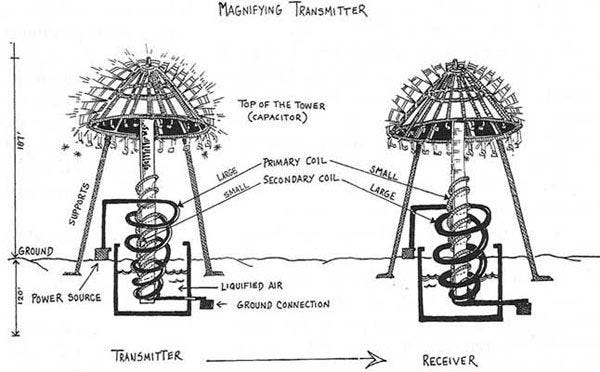
The second phase of his scaling plan was when he built the Magnifying Transmitter. He built this at his laboratory in Colorado Springs.
This was essentially a larger version of the Tesla Coil. Using it as an analogy, the first tower represents the primary coil, and the second tower represents the secondary coil.
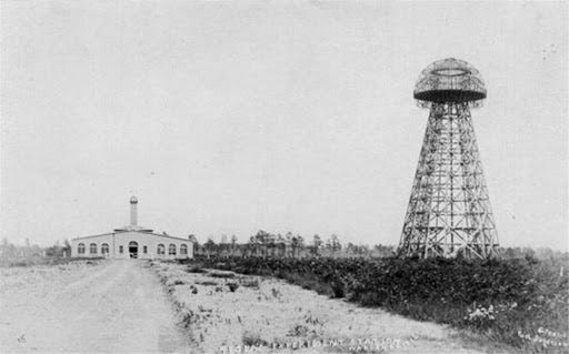
Finally, the third phase of his scaling was to take it global. He planned and built out the Wardenclyffe Tower in New York.
However, this version failed and was eventually taken down in 1917, but we’re getting ahead of ourselves. Let’s take a look at what needed to happen before Tesla came up with his very first demonstration; the Tesla Coil.
Historical Beginnings
To explain Tesla’s journey towards global wireless energy transfer, there are a few key points in history and inventions that we need to go over first.
The first key invention is that of the battery in the 1780s. Two physicists, Galvani and Volta, conducted an experiment. I talk about the entire process in my article about the physics behind wireless energy transfer. I’ve linked it below.
Following the battery, a Danish physicist named Hans Christian Ørsted learned that a moving electric current creates a magnetic field. His discovery was the first to find the link between electricity and magnetism. He demonstrated this in a lecture in 1820.
Perhaps the most important invention hereafter for the Tesla Coil is the electromagnet. In 1826, William Sturgeon, an English physicist, discovered that electric current running through a wire coiled around an iron bar caused the iron bar to behave like a magnet.
He fittingly named this the electromagnet.
A few years later in 1831, a man named Michael Faraday wondered if he could make electricity with magnets. So, he used electromagnets. Faraday is most well known for discovering electromagnetic induction.
He used two separate coils wrapped around one iron ring and noticed that when he attached/disconnected a battery to the first wire, the second wire would get a jolt of electricity. He called this inducing a current.
This phenomenon is explained using Faraday’s Law of Induction, which states that:
a changing magnetic field will induce an electromotive force (EMF) in a loop of wire, where EMF is what causes electrons to move and form a current
At this point, all of the components necessary to conceive of the Tesla Coil had been invented, but the background doesn’t end here.
What Was Innovated?
Following Faraday’s discovery of induction, Nicholas Callan, an Irish priest, wanted to improve Faraday’s device.
He decided to wind both the primary and secondary coils around the same iron bar while keeping them electrically separate. Doing this allowed him to feel electrical jolts from wire that had not been directly connected to a battery!
He also found that if the primary wire, the one connected to the battery, was thick and that the secondary wire was thin and had been coiled more, the jolt produced was more powerful.
If the secondary coil has fewer loops than the primary coil, the result is more current and less voltage. However, Callan’s made a secondary coil with more loops than the primary coil, so the result was more voltage and less current.
Callan’s device was named the Step-Up Transformer. When he connected the battery to a coil, it became an electromagnet with a magnetic field. When he disconnected the battery, it lost its magnetic field.
Using Faraday’s Law, every time Callan connected or disconnected, he created a new current in the second coil of wire. He also used a wheel to mechanically connect and disconnect the battery, acting as a kind of “repeater.”
Though this version was later improved by William Sturgeon, Callan’s device was used for electroshock therapy for many years.
The biggest advancement thereafter was using the coil itself to disconnect and connect to the battery instead of using the wheel. How did this work?
Well, the current running through the primary coil caused it to behave like a bar magnet. The wire carrying the current was then connected to a switch so that it could pull on it and activate a spring in the circuit.
The movement of the spring would turn off the current. However, once the connection was removed, the primary coil would no longer be magnetic. This causes the spring to disconnect, and the switch to turn back on.
An Electrical Interrupter
This process of the switch turning on and off would click about 20 to 40 times per second and was named an electrical interrupter.
There was still room for innovation.
The electrical interrupter would sometimes spark. So, in 1853 a man named Armand Fizau created the Leyden Jar to absorb the spark. It was the first version of a capacitor.
This is something made of two large conducting materials separated by insulating material.
By adding the capacitor and getting rid of the spark, Fizau created a new device — one that took DC from a battery and made bursts of AC in the 1850s.
Though not necessary to understanding the Tesla Coil, I’ll mention too that in 1886, Heinrich Hertz added an antenna to the induction coil and created the first man-made radio wave.
This is where Tesla comes in.
Tesla’s Take
Having heard of the radio waves created by Hertz, Tesla visited the World Fair in Paris, 1889. He began tinkering with the induction coil. Among other things, he removed the interrupter and DC battery and replaced it with an AC generator.
This makes sense — why use a battery and mechanical switch to turn the current on and off when a generator that automatically switches the current’s direction could be used instead?
Though this first adaptation didn’t actually work out at the end (due to overheating and melting of wire insulation) it did lead to Tesla’s use of a spark or air gap.
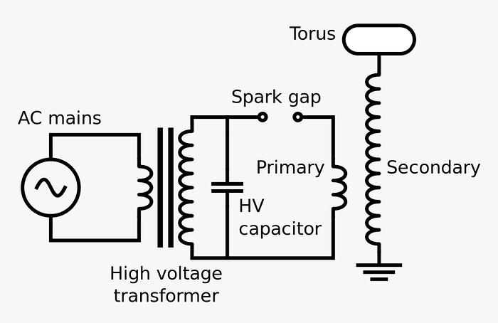
With a few other tweaks, we finally arrive at the original version of the Tesla Coil which looked something like this:
The Original Tesla Coil Circuit Uses Capacitors and Spark Gaps
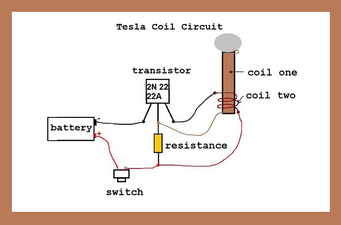
The modern version, which is what I recreated in my video, is slightly simpler. It no longer uses capacitors or spark gaps and looks like this:
Modern Version of the Tesla Coil Circuit
P.S. for an explanation of how electromagnetic induction works in the modern circuitry, watch my video linked near the beginning of this article.
Nikola Tesla wirelessly lit up a bulb in the year 1891 using his coil, but as I said earlier, his dream was to send wireless power over large distances by using the earth.
After the Tesla Coil worked, he built the larger version that I mentioned earlier called the Magnifying transmitter. It was able to light up three incandescent bulbs at 100ft or 30metres away.
Following his second success, he built the Wardenclyffe Tower in Long Island in 1901. He wanted to use the tower to harness the energy that he thought was inside Earth, in the hopes of turning our planet into a gigantic dynamo.
The tower would take energy from a coal-power generator and send it deep into the ground with a metal rod. He thought that the Earth’s crust would transport the energy.
The tower, however, was considered a failure, was taken down in 1917 and never finished. There are many speculations as to why it didn’t work, some more sound than others, of course.
The article I’ve linked below does a great job of explaining some of the flaws of the tower and how Tesla tried to address
There’s a lot left for us to develop when it comes to modern-day wireless energy transfer. We’ve only scratched the service, even with other methods like radio wave transmission and inductive coupling. To read more about how wireless energy transfer looks now, read this article I wrote.